Discovery 1 300tdi - no heater blower
Posted: Tue Feb 19, 2013 2:19 pm
Why do things always happen at the wrongtime, somebody's law no doubt. During the recent snow I decided to give the Disco a spin, it had not been used for a few weeks as I was enjoyihg driving around in the 600. With the snow I thought the disco might be a better option. For the past few years the Discovery ( 1995 300tdi ES) has been reliable so I wasnt expecting any problems. It started fine but during a brief drive the heater blower stopped. This had happened a few times before when the fan was on the fastest setting (4) and normally a quick reset to postion (1) on the slider control and then back to (4) and all was well. Not this time. Coincidentally during the same trip my daughter complained about water dripping on her feet while sitting in the passenger compartment.
Upon investigation, when the heater slider control was moved from (0) to (1) there was a clicking from a relay behind the glovebox on the passenger side. I investgated further and found that the passenger footwell was very wet, so wet that slight pressure on the mat, on the carpet produced water seeping out all over the door tread. I removed the trim from the passenger footwell, removed the carpet and also the moulded rubber sound deadening. This is basically a rubber cover bonded to about 1 cm of foam which makes a very good sponge. The moulding went over the transmission tunnel and appeared to be in one piece but I was able to make a cut, just below the trim on the tunnel to allow me to remove only the passenger side. This and the carpet were put out to dry and the floor mopped up. There were lots of signs of rust on the floor I dont know at this time if the floor is perforated thats another day.
I located where the relays were, on a hinged panel behind the glovebox where they were very wet, the relays just clip on this frame so I removed them all and let them hang loose. By operating the heater switch the clicking noise was indentified as coming from a larger relay covered with its own rubber shroud.

The print on the shroud identified it as:
Denso 058700-3300 with five pins, arranged in two rows.
I opened the relay up, taking off the rubber cover and the plastic case and it was FULL of black slimy water and metal dust, a bit like wet iron filings, one contact had completely disintegrated.
I went to my local LR dealer to get a replacement, which they had in stock for £55.00 , I refused this as I was sure there must be another way to sort it out.
The relevent bit of the circuit.( Note how the changeover works, earthing the blower when off, also the connection numbers)
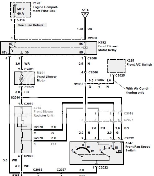
I looked at the circuit diagram for the blower and noticed it was a simple changeover or SPDT (single pole double throw) relay. By connecting together the wire from the heater to the feed from the fuse box, the blower came back to life, so hopefully a new relay was all that was needed.
Looking at the pin connections on the relay it seemed a little odd, there were two heavy duty connections and a smaller one, (ignoring the coil connections), it wasnt a standard chageover relay as then it would have equally rated contacts. Re-examining the circuit it showed the heavy duty contacts were used to connect the blower to the supply and the smaller connection was to connect the blower to ground. I am not sure why this is needed unless it is to provide a back emf to brake the blower fan when switched off. It did however show that a normal relay could be used instead.
I needed to know the rating of the relay so I bridged the blower and feed connections with a multimeter set to 10amps DC, the reading was 9.04A on fast(4). So a relay rated at 10A or more would do.
Note the other relays hanging down, and the rusty floor!

An ebay search found a suitable standard relay with connector and pins for less then £3.00 including postage. So all that had to be done was work out the connections.
Relay and base and connectors from ebay

For those who are interested the following are the connections required.
The original relay worked as follows:
Relay on (energised - fan on) positions (2 - 4)

The colours are the wire colours from the wiring loom and the numbers refer to the numbers on the circuit diagram.
Relay off (de-energised - fan off) position (0)

Wiring of replacement relay to do the same thing.
Note the numbers, 85,86 which are the coil and 30,87,87A which refer to the changeover switch and are also referenced on the circuit diagram within the relay enclosure shown on the diagram, the wires now have to transferred across.


Next post:
Making the connections and finding the leak
Upon investigation, when the heater slider control was moved from (0) to (1) there was a clicking from a relay behind the glovebox on the passenger side. I investgated further and found that the passenger footwell was very wet, so wet that slight pressure on the mat, on the carpet produced water seeping out all over the door tread. I removed the trim from the passenger footwell, removed the carpet and also the moulded rubber sound deadening. This is basically a rubber cover bonded to about 1 cm of foam which makes a very good sponge. The moulding went over the transmission tunnel and appeared to be in one piece but I was able to make a cut, just below the trim on the tunnel to allow me to remove only the passenger side. This and the carpet were put out to dry and the floor mopped up. There were lots of signs of rust on the floor I dont know at this time if the floor is perforated thats another day.
I located where the relays were, on a hinged panel behind the glovebox where they were very wet, the relays just clip on this frame so I removed them all and let them hang loose. By operating the heater switch the clicking noise was indentified as coming from a larger relay covered with its own rubber shroud.
The print on the shroud identified it as:
Denso 058700-3300 with five pins, arranged in two rows.
I opened the relay up, taking off the rubber cover and the plastic case and it was FULL of black slimy water and metal dust, a bit like wet iron filings, one contact had completely disintegrated.
I went to my local LR dealer to get a replacement, which they had in stock for £55.00
The relevent bit of the circuit.( Note how the changeover works, earthing the blower when off, also the connection numbers)
I looked at the circuit diagram for the blower and noticed it was a simple changeover or SPDT (single pole double throw) relay. By connecting together the wire from the heater to the feed from the fuse box, the blower came back to life, so hopefully a new relay was all that was needed.
Looking at the pin connections on the relay it seemed a little odd, there were two heavy duty connections and a smaller one, (ignoring the coil connections), it wasnt a standard chageover relay as then it would have equally rated contacts. Re-examining the circuit it showed the heavy duty contacts were used to connect the blower to the supply and the smaller connection was to connect the blower to ground. I am not sure why this is needed unless it is to provide a back emf to brake the blower fan when switched off. It did however show that a normal relay could be used instead.
I needed to know the rating of the relay so I bridged the blower and feed connections with a multimeter set to 10amps DC, the reading was 9.04A on fast(4). So a relay rated at 10A or more would do.
Note the other relays hanging down, and the rusty floor!
An ebay search found a suitable standard relay with connector and pins for less then £3.00 including postage. So all that had to be done was work out the connections.
Relay and base and connectors from ebay
For those who are interested the following are the connections required.
The original relay worked as follows:
Relay on (energised - fan on) positions (2 - 4)
The colours are the wire colours from the wiring loom and the numbers refer to the numbers on the circuit diagram.
Relay off (de-energised - fan off) position (0)
Wiring of replacement relay to do the same thing.
Note the numbers, 85,86 which are the coil and 30,87,87A which refer to the changeover switch and are also referenced on the circuit diagram within the relay enclosure shown on the diagram, the wires now have to transferred across.
Next post:
Making the connections and finding the leak


